Maintenance Case of Kalmar DCT Reach Stacker With Slow Hydraulic Action Of All Slings
Karma has launched rapid maintenance failure cases for seven consecutive years, helping customers solve various equipment failures and reduce equipment downtime. Karma will continue to share rapid maintenance failure cases on various social platforms this year, and will also release some research technical articles to help customers and maintenance personnel solve difficult problems, popularize locomotive technology theory, and further help customers improve productivity.
Fault Description
The customer said that all the hydraulic actions of the locomotive slings were very slow (including sideshift, 20 ‘- 40’ telescoping and opening/closing).
Troubleshooting
1. According to the preliminary analysis of the fault phenomenon, the possibility of locomotive hydraulic system fault is very large. If it is an electrical fault, there will be a fault code on the Karma electric control locomotive.
2. The pressure relief valve of the spreader pressure oil pipe was checked on site to ensure that it was normally closed.
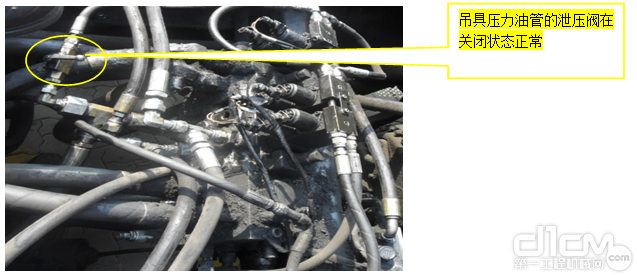
The pressure relief valve of the spreader pressure oil pipe is normal when it is closed
3. When the locomotive performs the hydraulic action of the spreader, use a hydraulic gauge to measure the pressure of the main hydraulic control valve of the spreader on site. The pressure is only 20bar at idle speed, and 50bar at throttle increase. The pressure is too low, which is very obvious. It is suspected that the oil supply of the spreader is intercepted and depressurized, causing the spreader to move slowly.
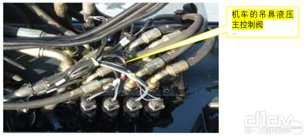
Main hydraulic control valve of locomotive spreader
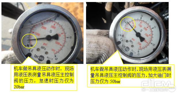
Pressure Gauge
4. After the Y6062-2 servo solenoid valve of the main hydraulic control valve of the frame is powered on, it controls the opening of the main oil supply valve core of the spreader to supply oil to the main hydraulic control valve of the spreader. The fault is checked according to the hydraulic schematic diagram of the DCT locomotive.
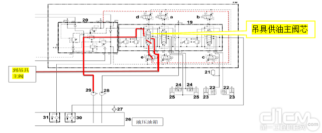
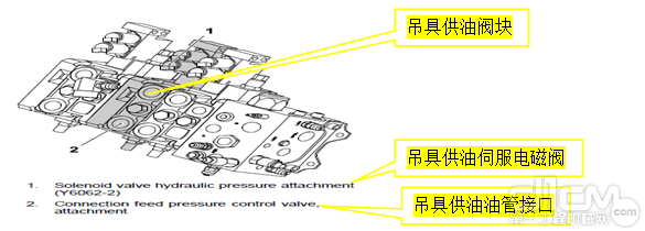
Illustration of oil supply description
5. On the premise that the hydraulic system is not disassembled, the visual comparison method is used to make a preliminary judgment: during the hydraulic action of the lifting appliance, the travel of the main valve core of the control lifting appliance oil passage valve section of the main hydraulic control valve of the frame is obviously shorter than that of the valve core during the forward and backward hydraulic action of the locomotive gantry, and the preliminary analysis is the internal problem of the lifting appliance oil passage valve section.
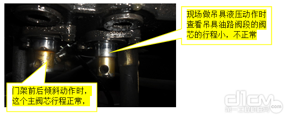
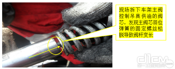
6. After the vehicle is stopped and the pressure is relieved, disassemble and check the oil supply valve block of the main hydraulic valve hanger of the frame on site, and check that the Y6062-2 servo solenoid valve is normal without jamming. When pulling out the main oil supply valve core of the spreader, it is found that the fixing screw of the return spring of the main valve core is loose, and the return spring is separated from the valve stem, which leads to insufficient travel of the main valve core when the spreader acts, causing insufficient opening of the oil supply channel of the spreader, and the oil supply of the spreader is intercepted and depressurized.
Resolvent
Clean the valve element, return spring and relevant accessories, replace the valve element sealing kit, coat the fixing screws with thread locking compound and retighten them in place. The commissioning inspection showed that all hydraulic actions of the spreader were normal, and the locomotive returned to normal use.
Case Summary
From the repair process of this maintenance case, we summarized that: if there is no fault code guidance when dealing with locomotive faults, we should analyze according to the control principle of the locomotive, find the most likely fault location for centralized troubleshooting, which can achieve twice the result with half the effort and reduce downtime. For hydraulic system fault, it is recommended to analyze the fault step by step according to the schematic diagram of locomotive hydraulic system.


